Agilix Solutions is an authorized distributor of Eaton’s B-Line series products and technologies. As a leading manufacturer of quality support systems and enclosures, for the electrical, mechanical, and communications industries, they are uniquely positioned as experts in their industry. We partnered with the Eaton B-Line series experts for this article detailing the NEMA standards for cable tray systems.
For those of you that have experience working with cable tray systems, you have probably noticed the high-level of influence NEMA has in guiding cable tray management projects. From establishing load classes and testing standards to recommending proper support of the tray, NEMA impacts the full scope of cable tray specifications.
Understanding the guidelines set forth by NEMA and how to utilize them is critical for ensuring that the right product is being chosen and used properly to help eliminate unnecessary installation costs. This summary should help decipher these NEMA guidelines and give you confidence in undertaking your next cable tray project.
What is NEMA?
The National Electrical Manufacturer’s Association, or NEMA, is the United States’ largest trade association of electrical equipment manufacturers. NEMA’s Cable Tray Institute is comprised of engineers from 12 cable tray manufacturers who meet to collectively set guidelines and recommendations for best product practices. These guidelines and recommendations can be found in the following standards that are regularly reviewed and issued by NEMA:
- NEMA VE 1 – “Provides technical requirements concerning the construction, testing, and performance of metal cable tray systems.”
- NEMA VE 2 – “Addresses shipping, handling, storing, and installation of metal cable tray systems. Information on maintenance and system modification is also provided.”
- NEMA FG 1 – “Covers construction and test requirements for continuous, complete nonmetallic systems of ladder, ventilated, solid bottom cable trays, or channel type trays, intended for the support of power or control cables, or both.”
This article will dig deeper into the standards for metallic cable tray systems and the impact they have on an end-user’s project.
NEMA VE 1
This first document is directed toward the NEMA manufacturers. It is the standard that addresses the construction, testing and performance of cable tray systems. Its primary purpose is to encourage standardization in manufacturing amongst the NEMA members to help eliminate misunderstandings between manufacturers and end users. These standards include areas such as material and coating types, safety factors and load testing.
For end-users, the most important standard within NEMA VE 1 is load testing. Its critical to understand cable tray testing and NEMA load classes to select the correct cable tray for the application.
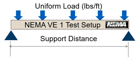
The image below depicts the typical NEMA load test.
This test consists of a single cable tray straight section supported in a simple beam scenario (non-continuous section supported at either end) with a uniform load applied across the rungs. This is the only NEMA load test for cable tray. Fittings, splice plates, and other accessories are not tested per NEMA VE 1. All tests are performed using the largest width and rung spacing for a particular series of tray. For ladder tray, this is usually a 36” wide tray with 12” rung spacing.
Results from this test will determine what NEMA load class or classes a specific tray series is grouped into. These classes are defined by a combination of a number which refers to the total span of the section being tested and a letter signifying the weight capacity per foot at that span.
Historically, NEMA has used four span categories (8, 12, 16, 20) and three load designations (A, B, C). For example, a “20C” tray is strong enough to support 100 lbs/ft of weight when the tray is supported every 20’.
However, tray load ratings are no longer limited to the four spans and three loads listed above. NEMA VE 1 now requires the marking on the cable trays to indicate the exact rated load on a particular span. For example, a tray may be rated for 150 lbs/ft on a 30’ span.
When designing cable tray, it is recommended to specify the required load, support span and straight section length to best match the installation. This information should be properly identified on drawings, specifications, quotation requests and purchase requisitions to help confirm that the cable tray with the proper characteristics will be provided and installed. (Note: The use of historical load class could lead to discrepancies between manufacturers.)
Secondly, it is also important to note that the load capacity given is a total load capacity; this does not apply only to the cable load. This includes environmental loads such as snow, ice and wind. These loads should be accounted for when designing a cable tray system.
The conformance to an industry standard in manufacturing and testing makes it vital to partner with NEMA manufacturers in each and every cable tray application.
NEMA VE 2
The second portion of NEMA’s metallic cable tray guidelines, VE 2, is designed to assist installers in the proper handling, storage and installation of cable tray.
While this document is full of valuable information, there are specific areas worth highlighting that generate the majority of questions on cable tray installations.
Straight Section Position
It is generally well known that the support span for straight sections should not be greater than the straight section length; this ensures that only one splice is located between supports.
Commonly asked: What is the best location for that splice joint?
Answer: NEMA VE 2 recommends that splice joints are placed at ¼ span from the nearest support location; meaning that if 12’ straight sections are being used, the ideal splice location is 3’ from the support. This method will impose the minimal amount of stress at the splice location and provide the least possible deflection in the tray.
Expansion Splice Joints
Challenge: Lack of expansion joints or improper installation of these joins is the leading cause of failure in cable tray installations.
Solution: To help eliminate these issues, NEMA VE 2 provides information on when and where expansion splice plates are required. This includes information on how to properly set the expansion gap based on the environmental conditions.
Fitting Supports
Commonly asked: What is the correct method for supporting cable tray fittings?
Answer: NEMA VE 2 provides recommended practices for each fitting type. However, this guideline also contains a very important clause: “or as recommended by the manufacturer”.
As previously mentioned, NEMA is made up of several manufacturers, each of which offers a product with varying capabilities. The recommendations within NEMA are applicable to every manufacturer within the organization, but each manufacturer may also offer alternative recommendations specific to their product.
Agilix Solutions and Eaton B-Line Series – Expertise You Can Count On
The above summary highlights only a small portion of the wealth of information NEMA can assist with on a cable tray install. To download NEMA VE 2 in its entirely or to review a list of frequently asked questions, visit https://www.cabletrays.org/ for more info. For more information about Eaton’s B-Line series cable tray solutions, visit Eaton.com/cabletray.
You’re never more than a click or call away from the experts with Agilix Solutions. Reach out to your account manager or nearest branch location with any questions.


